Replacing A Technic 1200 Tone Arm & RCA Wiring
Let’s face the facts, at some point in your turntables life you will need to replace the tone arm or even re-wire a bad RCA connection. We are not all jedi masters in the ways of electronics and the knowledge to troubleshoot in the world of Electronics. However just about any safe person, noticed I stated ‘Safe’, can replace a bad Tone Arm on their Technics or even re-wire a bad RCA connection! The procedure is rather simple and takes about 30-45 mins to complete and in most cases it only takes me 15 mins to replace a full Tone Arm.
There are a few things which need to be squared away first. Be sure to have the following items ready to help speed up the overall process, plus it makes things a hell of a lot easier.
Tools
- Solder Gun (with De-Solder Option is a plus if you know advance soldering). However not really needed
- OK, do not get freaked out just yet! Soldering is rather simple and you can always get help from Google, Youtube, or other online search engines. If you are not comfortable with soldering, try practicing on some old boards! Even Radio Shack sells starter kits and boards to practice with.
- De-Solder is just a suction tool which can range in different appearances. In short it removes the old soldering. Again this is not required, you can use the existing solder beads.
- 1 Philips Head Screw Driver (Magnetic if possible)
- 2 Flat Head Screw Drivers (Magnetic if possible)
- One Regular Size
- One Thin, like the ones used for Eye Glasses or Watches.
- Cups, Bowl, Dishes… anything to keep screws in along with Labels or Tape
- Books, DVD Cases. Basically you want anything with will prop up the table. We’ll get to that part quick.
- Pen And Paper for Labeling.
- This Guide
Remember!!
If you do not solder well you can always opt out and go to a local electronic store and have them do that portion. Bottom line.. fixing tables is rather simple and is not too hard. It is a great way to learn while saving $$.
Important!
And here comes my little words of warning! I take no responsibility for your human mistakes, errors, or in short fucking up your tables. This guide is here to help you replace the tone arm and get you to the point of re-wiring if needed. If you are not comfy with the procedures, then take your babies to a professional!
Now let’s proceed!

- Get your turntable READY!

1. Grab your DVD’s/Books or in short anything which will prop up the tables. I found that a good 4 – 5 DVD’s per corner of the turntable works well, like turntable jack stands 😉

2. Take your DVD’s or what ever you are using and place them in a four corner pattern. Be ready to slide catch a dropping platter!! Then place your turntable on them upside down. (This helps the platter drop out! Which should be removed from the table.)

3. REMEMBER. You want to make sure the Tone arm is clear from the floor, table, or where ever you choose to perform the procedure.

4. Unscrew all four legs. Place them aside in a safe location.

5. Grab the Philips Head, Grab your first cup and Label it “Bottom” or some label you can ID with. Then unscrew all the screws. There are a lot, be sure to note the different washer & screws; some are small and some are larger.

6. Using the Flat Head Screw Driver, Carefully pry the Rubber bottom (black) off the Turn Table. This can be done by hand but I find the flat head works better.
a. Remove the Power and Turn Table RCA/Ground Wires and place the Rubber Bottom in a safe location.
b. This is a great time to also Clean any dust from the black bottom.

7. Using the Philips Head Screw Driver, Carefully unscrew the 4 Screws shown above. Place these screws in to a new CUP or safe location; Label them so that you can ID the proper screws. (Label Step 7 or something…)

8. Once you have the screws undone you will need to wiggle this part loose. The part clamps going into the tone arm.
a. This is a fail safe in case some groupie comes close to the table and yanks out the RCA Cord, ground wire, and power plug. It saves your turntables from ripping clean of the board where the wires are soldered to.

9. Here is a close up of the clamp. Wiggle this part, makes life easier.

10. Here is a close up of the clamp. You may also use a Slim Flat Head to un-clamp this section. This helps loosen the clamp as well.

11. Pull back the Metal Door and you are almost there. Note you see the Black Felt tape? This tape is used to protect both the solder and wires for the tone arm & RCA cables. Peel it off and put it to the side, you will need to reapply the tape. (Note: Sometimes this tape wears out or is not able to be reapplied. Simply use electric tape or even masking tape to re-cover solder upon completion)
- You would de-sod / re-sod each connection on the board with wires here!
- There are several connects to note, L- (Left Negative) / R- (Right Negative) as well as L+ (Left Positive) / R+ (Right Positive)
- It is a good idea to take out your Pen and Paper, Jot down which colored wires go Where! You could even draw a simple diagram of the Board and use it when re-soldering occurs, that’s later down the line BTW.
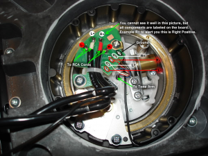
Click for Turntable Tone Arm Wiring Details

12. Here you see the wires going into the tone arm!
a. Unscrew the two screws marked above while holding the tone arm.
b. Holding the tone arm is to prevent it from falling out and being safe, so please HOLD it while unscrewing these two screws.
c. Again you should have a new cup or a place to keep these screws!

13. Now, we are back at the top of the table. Just pick it up slow and unscrew the following with a Slim Flat Head Screw Driver…wiggle the part labeled in blue.

14. Here is a close up of the part which should be wiggled loose.
a. Note: this part uses two Pivots, one which is unscrewed with the “thin” flat head screw driver. The other should NOT be touched, it lays on the bottom of this device shown above.

15. Here is the tone arm. Loose and in ready to be pulled!
a. At this point the wires should be de-soldered
Now reverse steps to install. Feed wires back in.. Use the diagram you made to solder the proper wires on the the Board. Screw everything back up!
Now that was not too hard was it?
You have learned and saved money, which is the best point about this whole procedure. Installation of turntable components is rather simple and the more you play with them. The more you will be comfy with installation and basic remedies for issues such as this.
If you found any issues with the procedures above or would like to add to the procedures, please contact us! We are always down to pass the best knowledge to our readers!